Project overview and constraints
We needed to build a device that would spin a motor, until detecting a jam by blocking 2 adjacent LEDs. Blocking 2 LEDs would make a LED on the chip light up, make the motor stop moving, and set off a buzzer. We also needed a reset button to stop the buzzer from making noise.

Circuits
Fischertechnik Kit, SN754410 chip, External Power Supply, motor, XS6CSX4 PLD Chip, Breadboard, Micro USB cable, 5.6k resistors, and wires
We used the resistors to reduce current that is going to the LEDs on the Fischertechnik Kit.
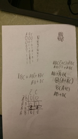
We needed a combinational logic circuit to detect when the copier would be jammed. We needed to make the printer only jam when two LEDs, which are adjacent to each other, or three LEDs were blocked. This would trigger the buzzer, LED, and the stoppage of the motor.
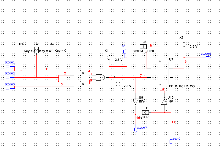
We needed the flip flop to make sure that the buzzer would keep going until the reset button was pushed.
The LED is connected directly to the inputs so its only on where there is a jam. The buzzer is connected the flip flop so it keeps going until you hit the reset button.
We needed the motor driver is needed to run the motor and connect it to the PLD chip.
We used the resistors to reduce current that is going to the LEDs on the Fischertechnik Kit.
We needed a combinational logic circuit to detect when the copier would be jammed. We needed to make the printer only jam when two LEDs, which are adjacent to each other, or three LEDs were blocked. This would trigger the buzzer, LED, and the stoppage of the motor.
We needed the flip flop to make sure that the buzzer would keep going until the reset button was pushed.
The LED is connected directly to the inputs so its only on where there is a jam. The buzzer is connected the flip flop so it keeps going until you hit the reset button.
We needed the motor driver is needed to run the motor and connect it to the PLD chip.
Conclusion
In this project we used several items that were programmed by the PLD chip instead of just a display or LEDs. We learned how to power and connect a motor, we learned how to use several components in a circuit, and how to have different components running at different times such as the LED and buzzer.
