
We had to make a counter that used two seven segment display that would count up to 80 by using a counter or a button. You also had to be able to reset it.
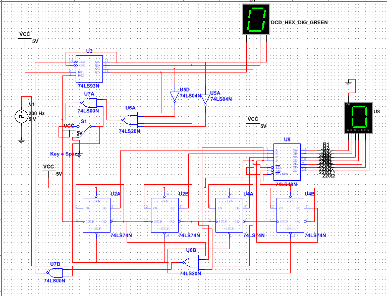
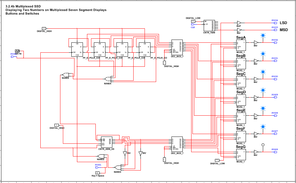
The different between design mode and PLD mode are the components and setup. In the design mode we used the seven segment displays, counters, and SPDT switches. In the PLD mode we had to use PIO's because we would wire the chip into the switches and buttons on the board. We also used the PIO's for the outputs such as the segments of the 7 segment display. Design mode is just used to see if the circuit will work and the PLD mode is used to be imported into the programmable chip which is then wired.
Bill of materials
- myDigital Protoboard
- National Instruments myDAQ
- Cmod S6 chip
- 15 Wires
- Micro USB cable
- Type A to Type B USB cable
- Power source
Conclusions
1. Difference between SSI and MSI circuits: SSI circuits use the D flip flops and are more customizable. They can be an up counter or a down counter. You can also change what number it starts at. MSI circuits can't be preset to a certain number to start at and they can only be a down counter.
2. Limitations of MSI circuit you created: It can't count past 15.
3. Meaning of "rippple effect": This occurs between the gates which delays the signal and can disrupt the output/display.
4. Set up of your design: My circuit contains a SSI circuit which controls the ten's place, and a MSI circuit that controls the one's place. They are connected to a reset switch that would set both displays to 0 when flipped. My counter was controlled by a button that makes the counter go up by 1 each click. The one's counter goes from 0-9 and then resets to 0 and a 1 would be added to the ten's place and this would continue to 80 and stop.
5. Difference between other students: My circuit was controlled by a button instead of a counter like some other students had for their circuit.
